What Is a Shear Connection?
A shear connection is a joint designed to carry shear forces without transmitting a bending moment. While this description holds in theory, pure shear is an idealization and there are situations where a bending moment accompanies the shear force. This is a factor structural engineers need to account for when sizing the connection.
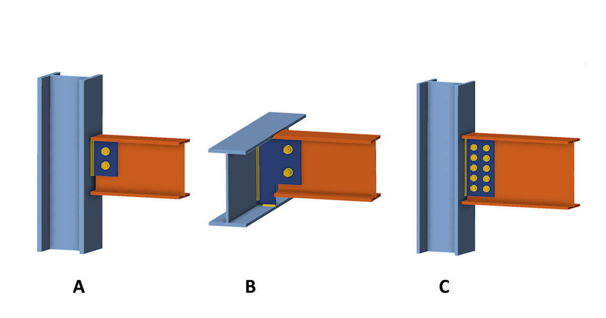
The following covers three typical configurations where an I-beam is connected to a column or supporting beam using a vertical fin plate. Each behaves differently when transferring loads.
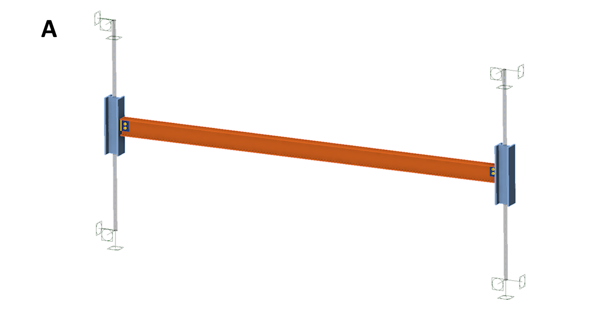
Connection A
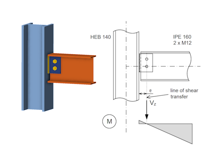
Connection A is a standard simple shear connection in which a horizontal beam is fixed to a column by a fin plate with a small number of bolts in a single line. The rotational stiffness of this connection is very small. Accounting for bolt hole tolerances, it is standard practice to treat the connection as pinned. The bending moment at the connection point is zero, and the bolts carry only the vertical shear force. The weld connecting the plate to the column carries both the vertical force and a bending moment equal to the vertical force multiplied by the eccentricity.
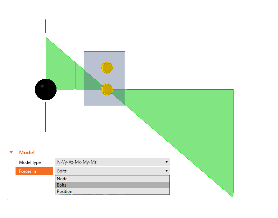
In IDEA StatiCa Connection, this configuration is modeled by entering only the vertical shear force and positioning the load at the center of the bolt group.
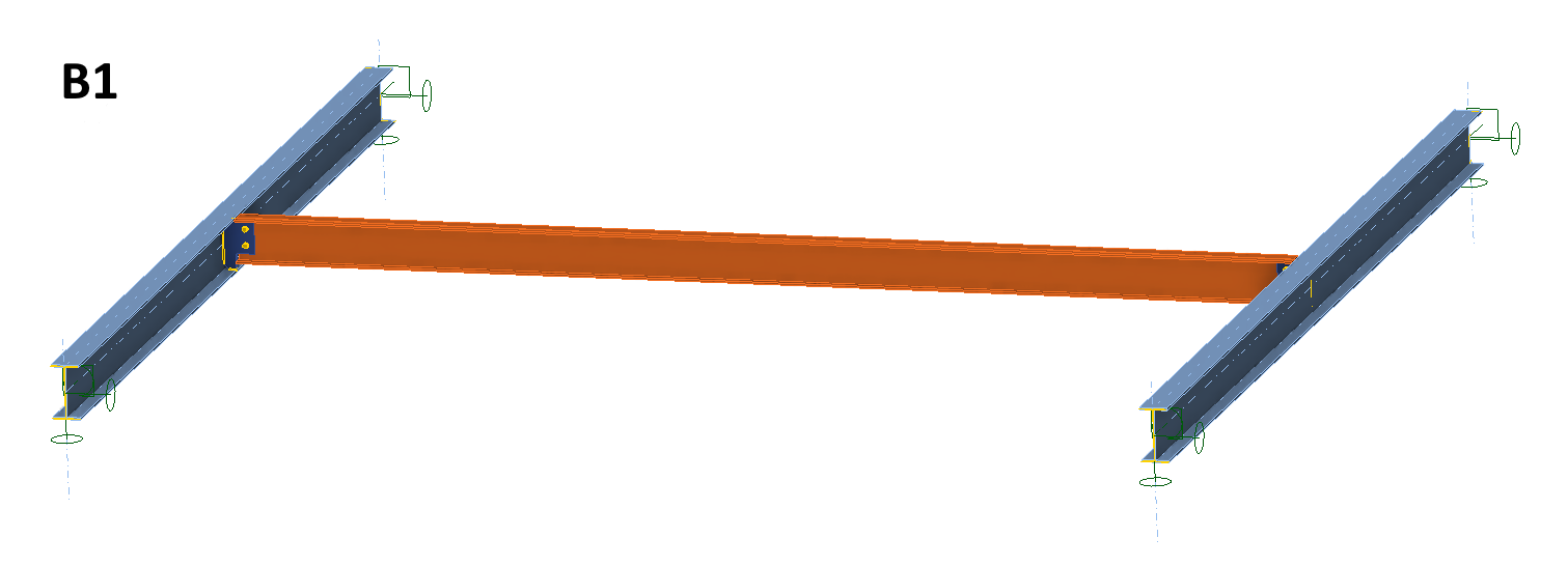
Connection B
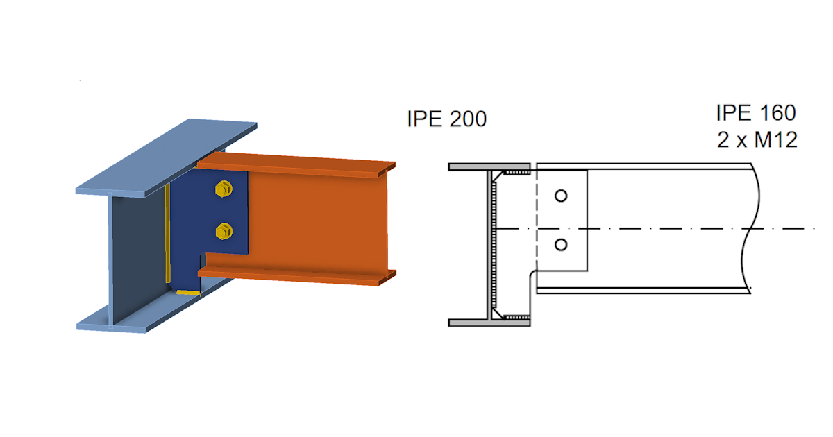
Connection B is another type of simple shear connection, where the I-beam attaches to a perpendicular supporting girder. Assuming the girder has no rigid floor slab above it and its top flange is free to move horizontally, the torsional flexibility of the girder changes how the connection behaves compared to Connection A.
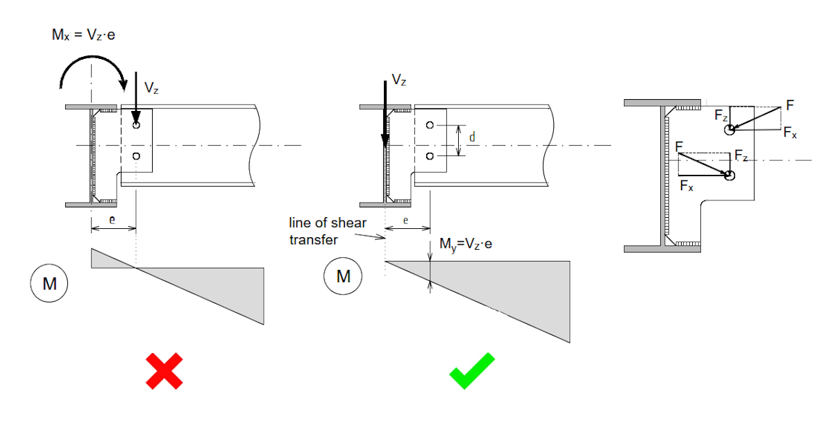
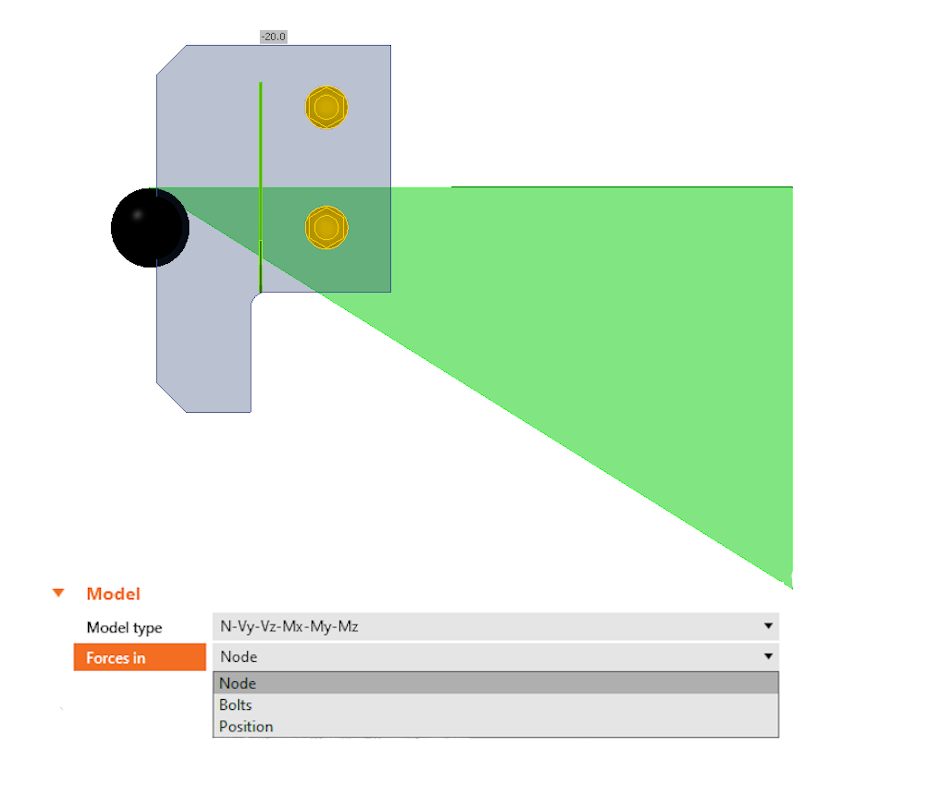
If the girder has very low torsional stiffness, it cannot transfer the torsion moment to its supports. Instead, the girder twists and the bending moment redistributes. In the limiting case, there is zero moment at the girder axis, meaning the bolted shear connection is loaded by a bending moment. This moment has a significant effect on the bolt forces. In IDEA StatiCa Connection, this is modeled by placing the load position at the node rather than at the bolt group center.
Where the torsional stiffness of the girder is not negligible, the behavior shifts toward Connection A. This is especially true for connections located near the ends of a girder, where torsional restraint from the supports limits the ability of the cross-section to twist. On a single girder supporting multiple parallel beams, connections near the supports may behave like Connection A while those at midspan behave like Connection B.
Connection C
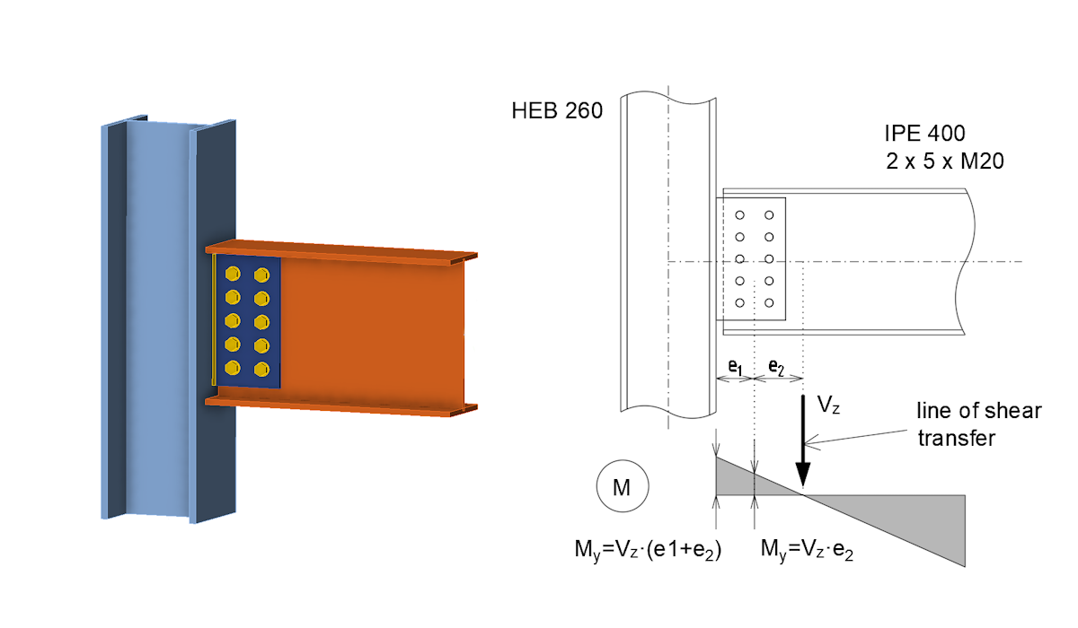
Connection C is a larger single plate shear connection, such as five bolts in two rows. This connection can have considerable rotational stiffness, which affects the distribution of internal forces. The point of zero bending moment shifts toward the midspan of the connected beam and a negative bending moment acts at the center of the bolt group. The magnitude of this moment depends on the rotational stiffness of the bolted connection.
If the connection is classified as pinned and has sufficient rotational capacity, the small bending moment it transmits can be ignored and forces distributed as for Connection A. If the engineer does not apply this simplification, or if the connection is classified as semi-rigid, the calculated rotational stiffness must be included in the global analysis model and the connection verified for both shear and moment using IDEA StatiCa Connection.
Verification Using IDEA StatiCa Member
IDEA StatiCa Member allows accurate modeling of steel structures or parts of structures using shell elements in 3D. Connections are modeled using CBFEM, incorporating bolts, connection plates, welds, and other components directly into the computational model.
Connection A
A structure of two HEB140 columns with an IPE160 beam connected by Connection A, spanning 4 m under a load of 10 kN/m, shows almost zero bending moment at the bolted connection. The bending moment diagram corresponds well to the theoretical analysis.
Connection B
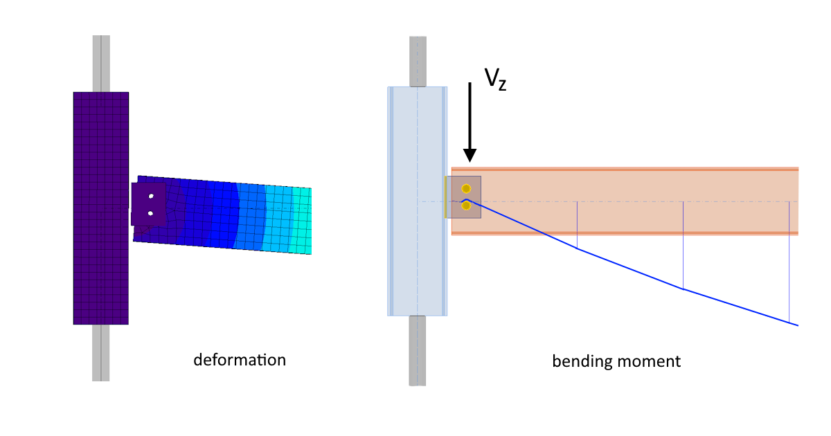
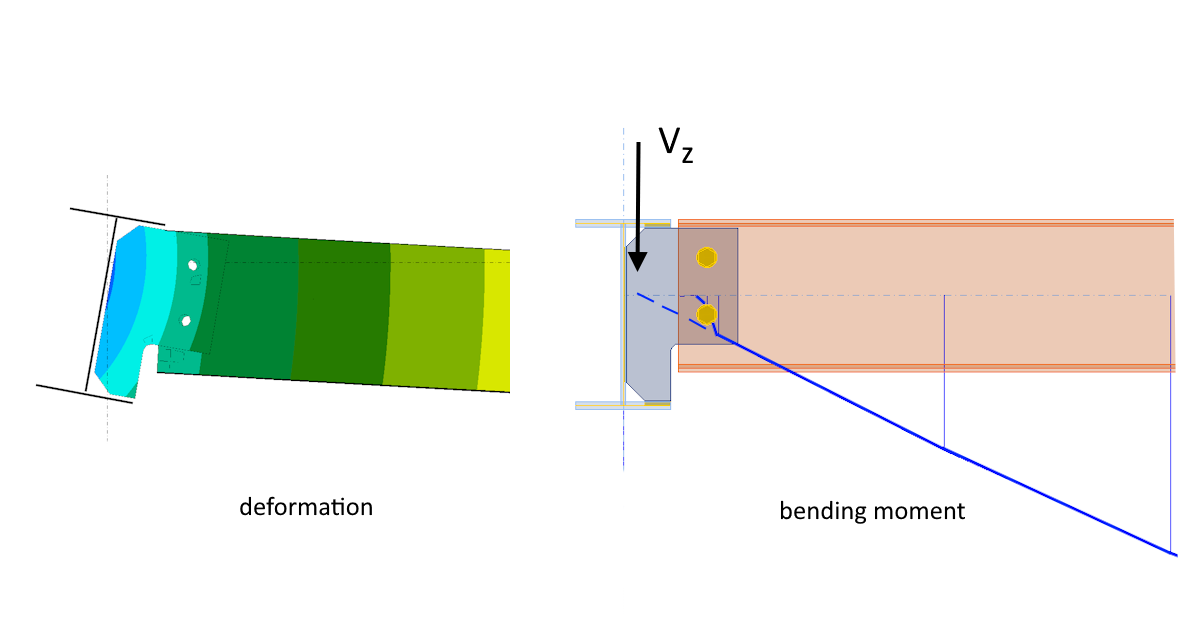
For Connection B, using IPE200 girders and an IPE160 beam under 10 kN/m, the bending moment at the bolt position is positive. The total shear force in one bolt from combined vertical shear and bending moment reaches 31 kN, three times the 10 kN value from vertical shear alone. Neglecting the moment in a Connection B design could lead to a significant underestimate of bolt demand.
When the same beam is positioned 0.5 m from a girder support, the moment diagram shifts and the zero moment occurs near the bolt group center, confirming that connections near supports behave like Connection A.
Connection C
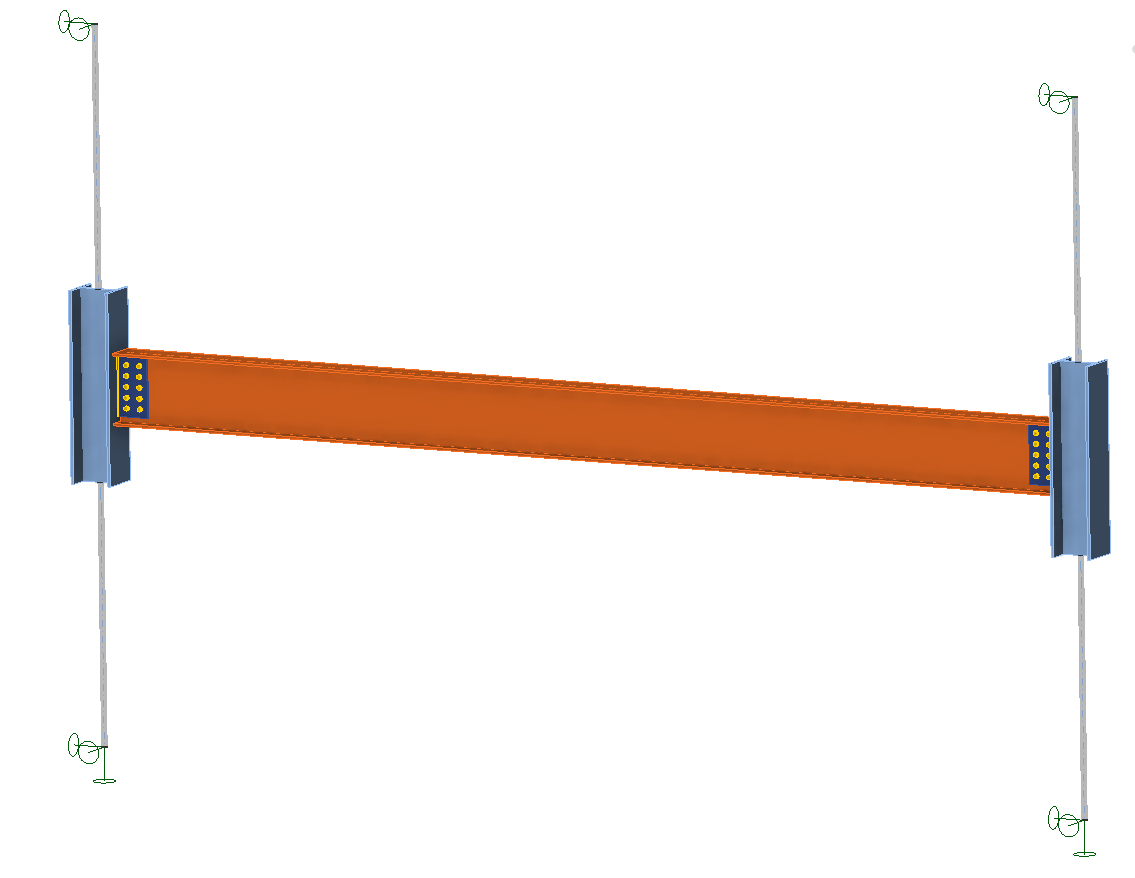
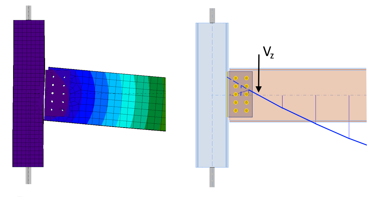
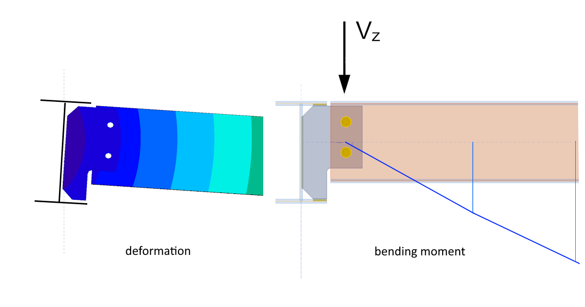
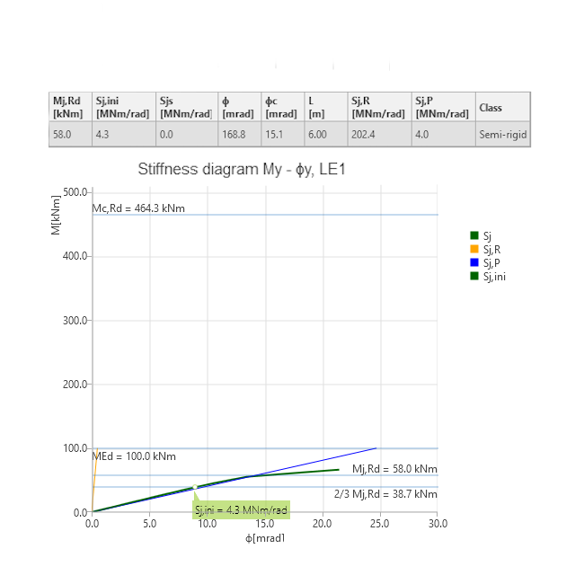
For Connection C, using HEB240 columns and an IPE400 beam spanning 6 m under 80 kN/m, the Member application shows a negative bending moment at the bolt group. Stiffness analysis in IDEA StatiCa Connection classifies this connection as semi-rigid, consistent with the theoretical prediction.
Conclusion
Shear connections appear straightforward but can behave very differently depending on where they appear in a structure. IDEA StatiCa Connection and Member together allow engineers to analyze the real behavior of the connection in context and obtain safe, code-compliant results.