Why HSS Connections Are Different
Steel is well suited to visible bearing structures. When hollow structural sections (HSS) are used in an exposed application, the goal is often fewer and smaller connections. Welded connections are preferred over bolted ones. The minimal, clean appearance that appeals to architects and designers is, however, a real challenge for structural engineers, fabricators, and erectors.

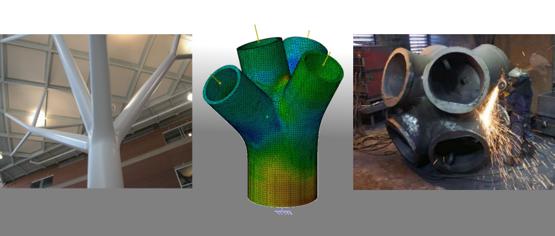
The Beijing National Stadium is a well-known example of HSS members used in an iconic architectural application. The cross-section choice had a direct impact on the overall appearance of the structure.
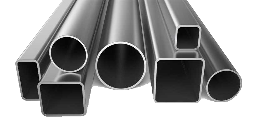
Standard HSS Shapes
The HSS family includes rectangular hollow sections (RHS), square hollow sections (SHS), circular hollow sections (CHS), and, in some cases, elliptical sections.
Common Applications
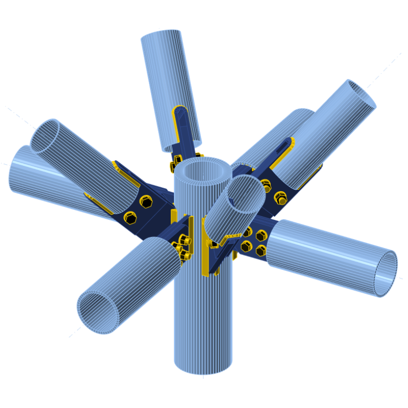
HSS members are used across a wide range of structural applications, with the most common being columns, braces, trusses, and curved beams.
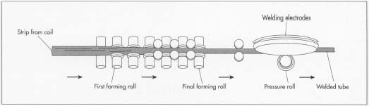
How HSS Members Are Manufactured
Hollow sections are produced by two methods. In cold-formed or rolled and welded production, sheet metal is bent into the required shape and welded into a closed section. In continuous milling, the base material is heated to a white-hot state, formed into a cylinder, and a bullet-shaped piercer point is pushed through to form the hollow core.

Advantages of HSS Members
HSS members offer several structural and practical benefits. Their appearance is cleaner than open sections. They generally weigh less per meter and have a smaller surface area, reducing finishing costs. Torsional resistance can be up to 200 times greater than equivalent open sections such as I, C, L, and T shapes. Compression capacity is also higher for the same unbraced length. HSS can be used as jackets around concrete columns to increase axial capacity, and they are available in a wide range of standard sizes.
Disadvantages of HSS Members
HSS members are not well suited to flexural applications because more steel is required compared to an equivalent I-section. Bolted connections are difficult to install because the closed section prevents access from inside.
Design Codes and References
Key references for HSS connection design include AISC 360 Chapter K, AISC Design Guide No. 24, the CISC Design Guide for hollow structural section connections and trusses, EN 1993-1-8 Chapter 7, the CIDECT Design Guides, and the Steel Tube Institute HSS Design Manual Volume 3.
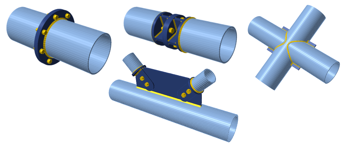
Bolted Connection Options for HSS
Making an HSS connection bolted introduces several challenges. Using through bolts risks flattening the hollow section during tightening. Threading the hollow section wall may not provide adequate tension resistance. Welding a nut to the inside face adds cost and is not always feasible in narrow sections. Several fastener systems address these limitations directly, including blind bolts, hollo bolts, and structural nut keepers such as the SHURIKEN system.

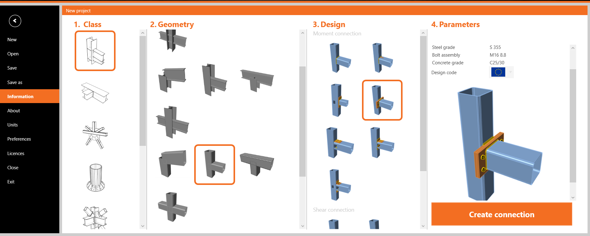
Designing HSS Connections in IDEA StatiCa
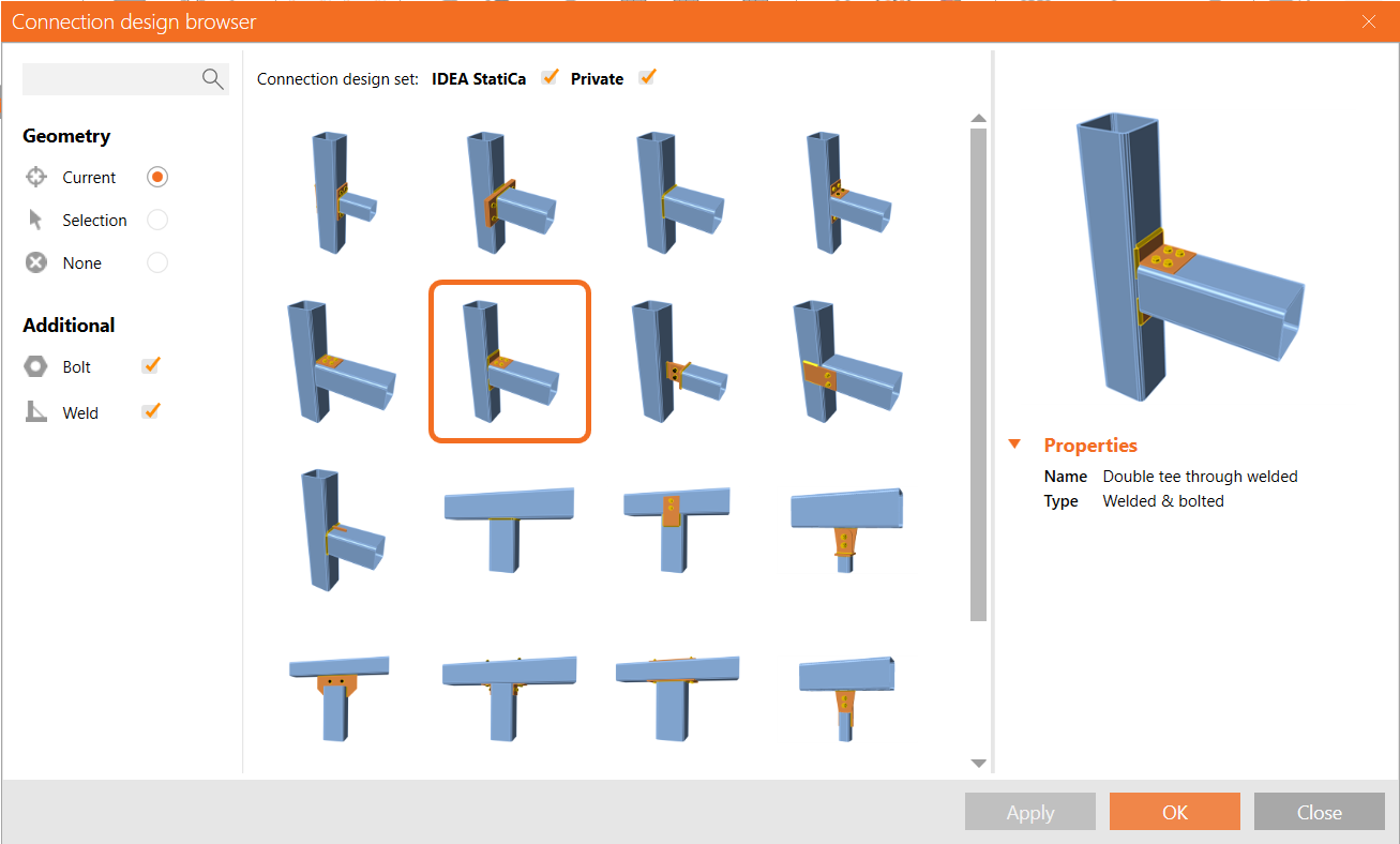
IDEA StatiCa Connection includes a starting wizard with dozens of templates covering common HSS configurations. From there, the right-click Connect to feature opens a connection browser containing both standard sets and user-defined designs. Suitable options for the specific geometry appear within seconds.
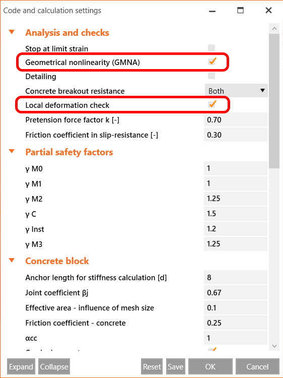
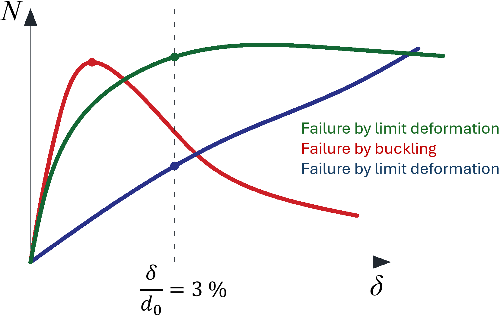
Local Deformation and Failure Mode Checks
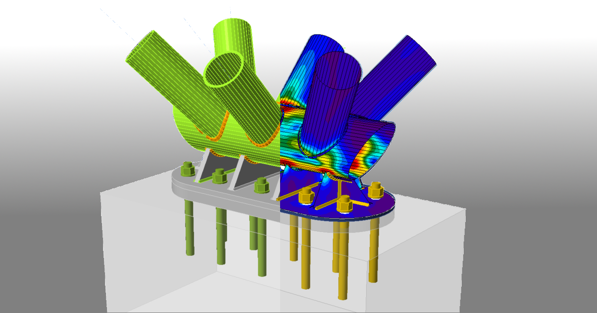
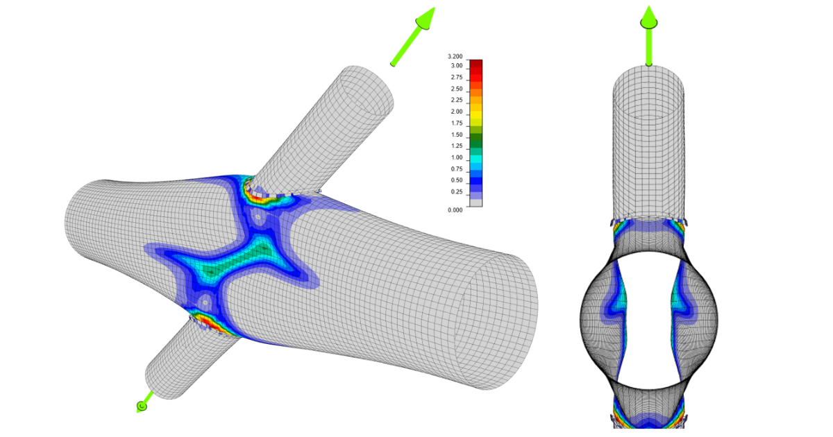
One frequently overlooked aspect of HSS connection design is the local buckling failure check for hollow members. IDEA StatiCa Connection includes a checkbox in the Code setup dialog that activates the local deformation check as part of the connection analysis.
Thin-walled and standard hollow section members have distinct failure mode differences. The theoretical background for joints of hollow section members is documented in the IDEA StatiCa support center.
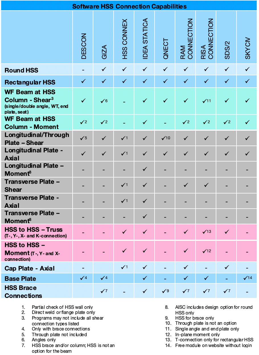
Software Comparison
An overview of connection design software capabilities for HSS connections was published by the Steel Tube Institute. IDEA StatiCa Connection was identified as the only tool based on the finite element method, capable of modeling any connection geometry. It was also the only application satisfying all the evaluated criteria in the comparison.