Overview
IDEA StatiCa Connection and Detail are linked by a BIM connection that allows anchoring models to be transferred between the two applications. This tutorial covers the full workflow for designing and code-checking a reinforced concrete block with eccentric loading according to Eurocode, using the combined capabilities of both applications.

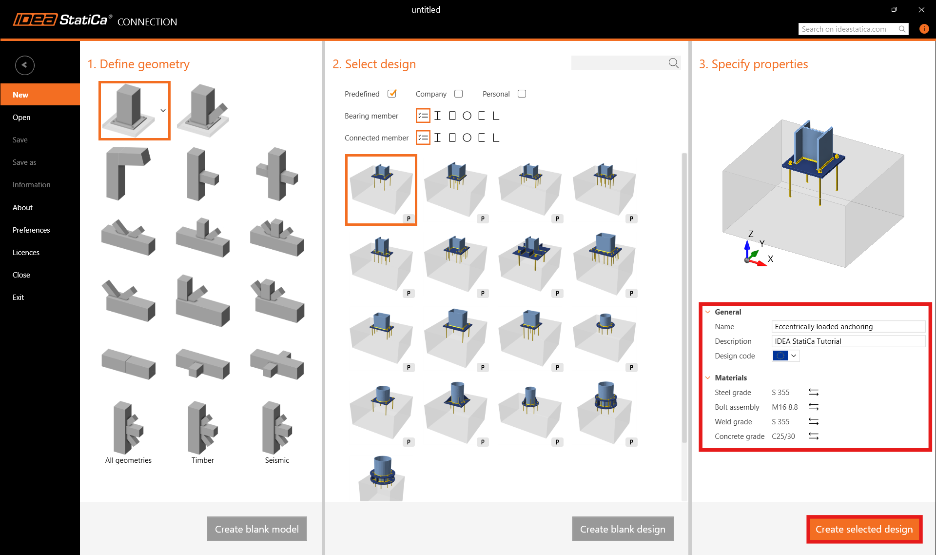
Step 1: New Project in Connection
Open IDEA StatiCa Connection and begin on the Steel card. Keep the default settings for the anchoring topology and open the application.

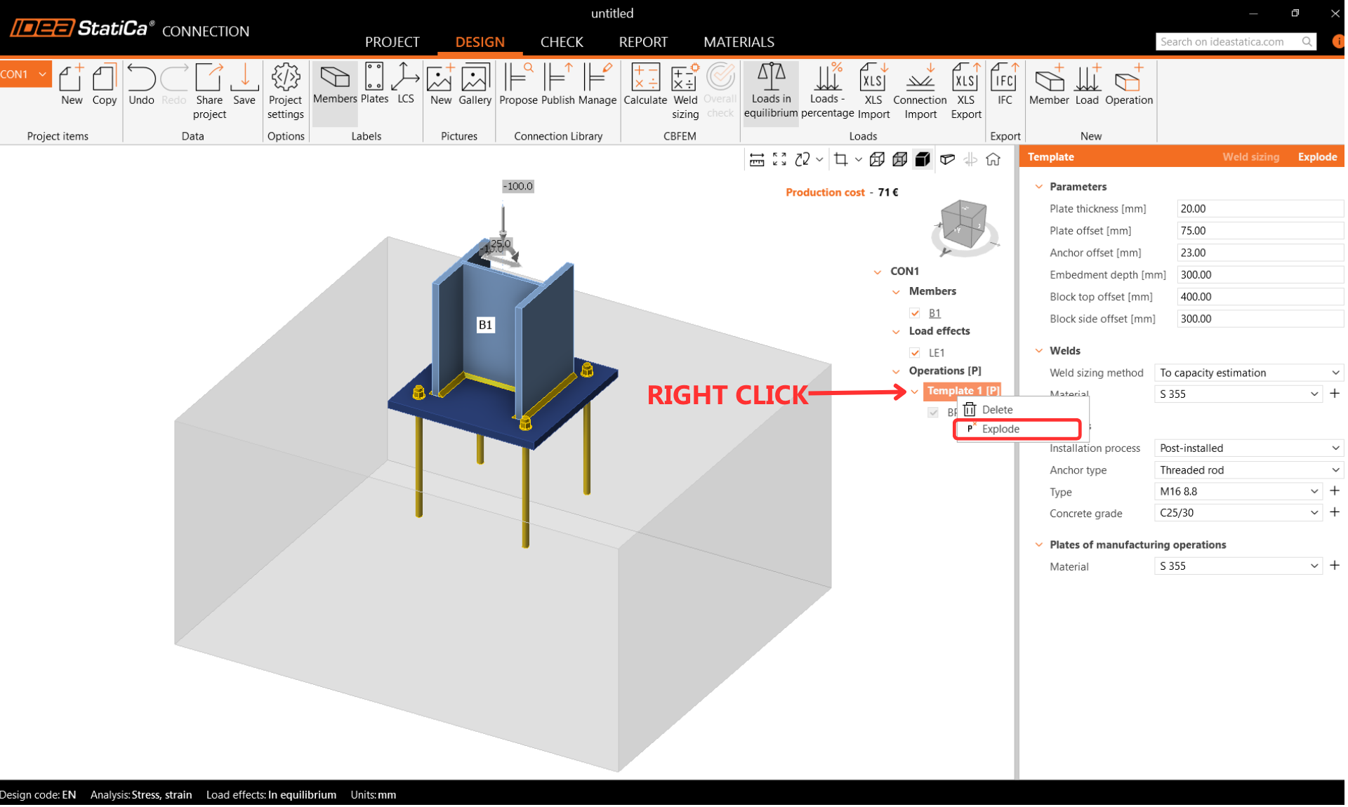
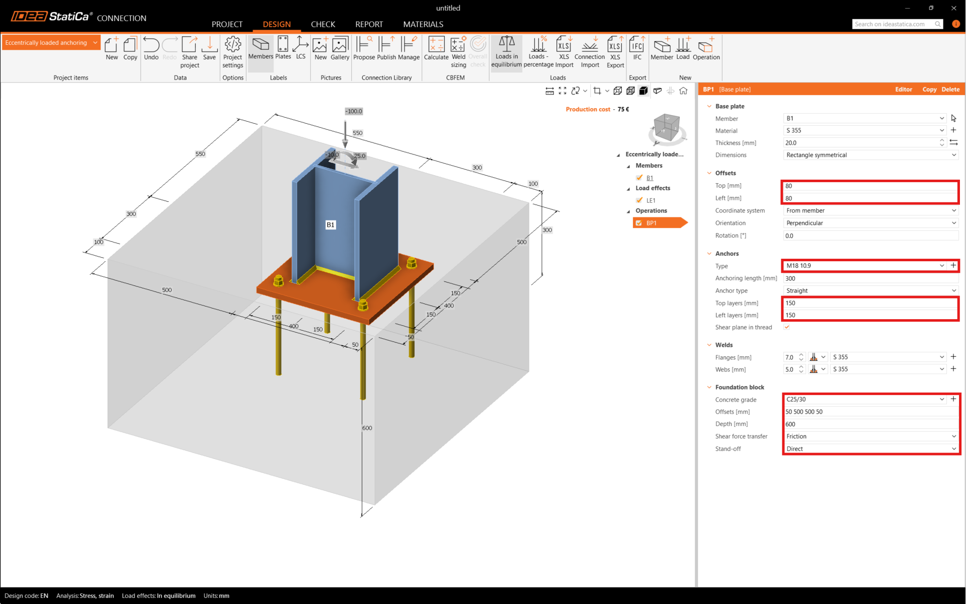
Step 2: Design the Anchoring
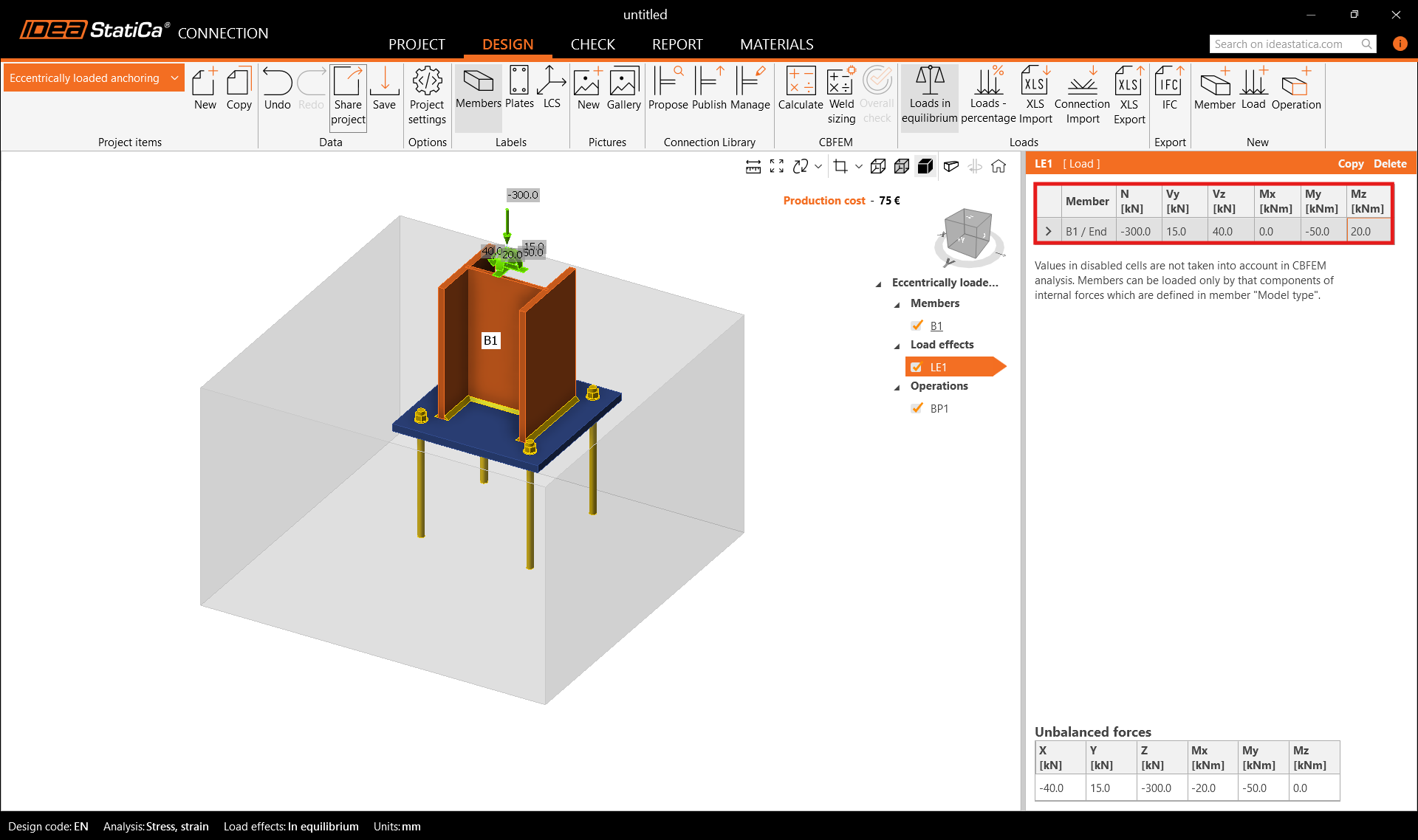
After creating the solution from the template, explode the template into separate operations to allow repositioning of the footing toward the concrete edge. Adjust the base plate and set the shear force transfer to friction. Then input the internal forces for biaxially loaded anchoring. The internal forces produce compression stress at the contact between the ground and the concrete block. By default, the concrete block is treated as cracked.
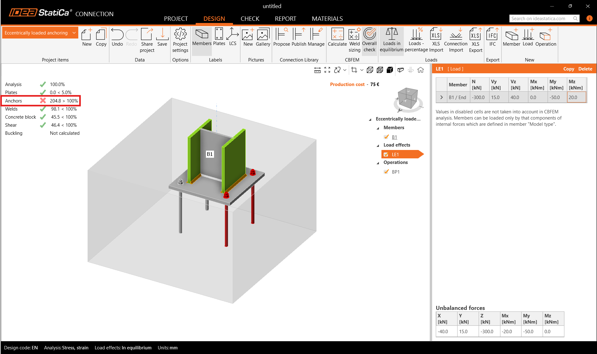
Step 3: Calculate and Review Checks in Connection
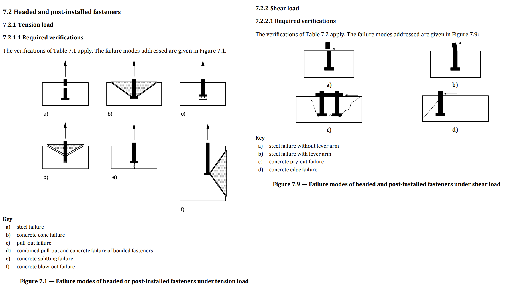
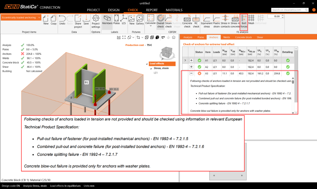
Go to the Check card and calculate. Review the failure mode output on the anchors. Examine the detailed anchor check results, which identify a nonconformity on the first page. This alerts the engineer to checks that cannot be performed in IDEA StatiCa Connection and must be addressed in another way. The problem is caused by concrete breakout resistance in tension and shear. IDEA StatiCa Detail, which uses the 3D CSFM method, can resolve this failure mode by accounting for reinforced concrete rather than plain concrete.
Step 4: Export to Detail
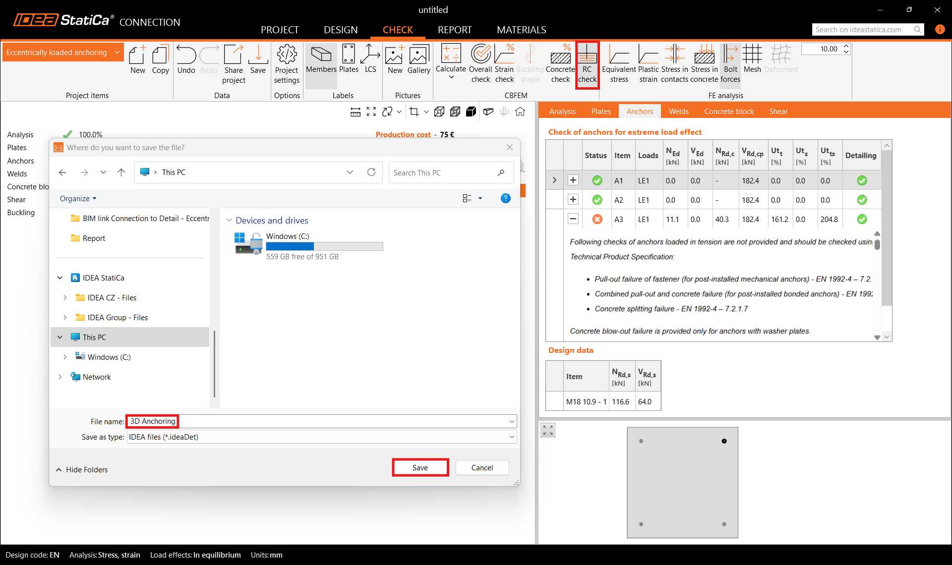
IDEA StatiCa Connection includes a direct BIM link to Detail. The model must be calculated before the export is enabled. Go to Check, then RC check, then Save. The export transfers the concrete block, anchors, base plate, loads, shear transfer settings, material properties, anchorage type, and friction coefficient to Detail.
Step 5: Design in Detail
Supports
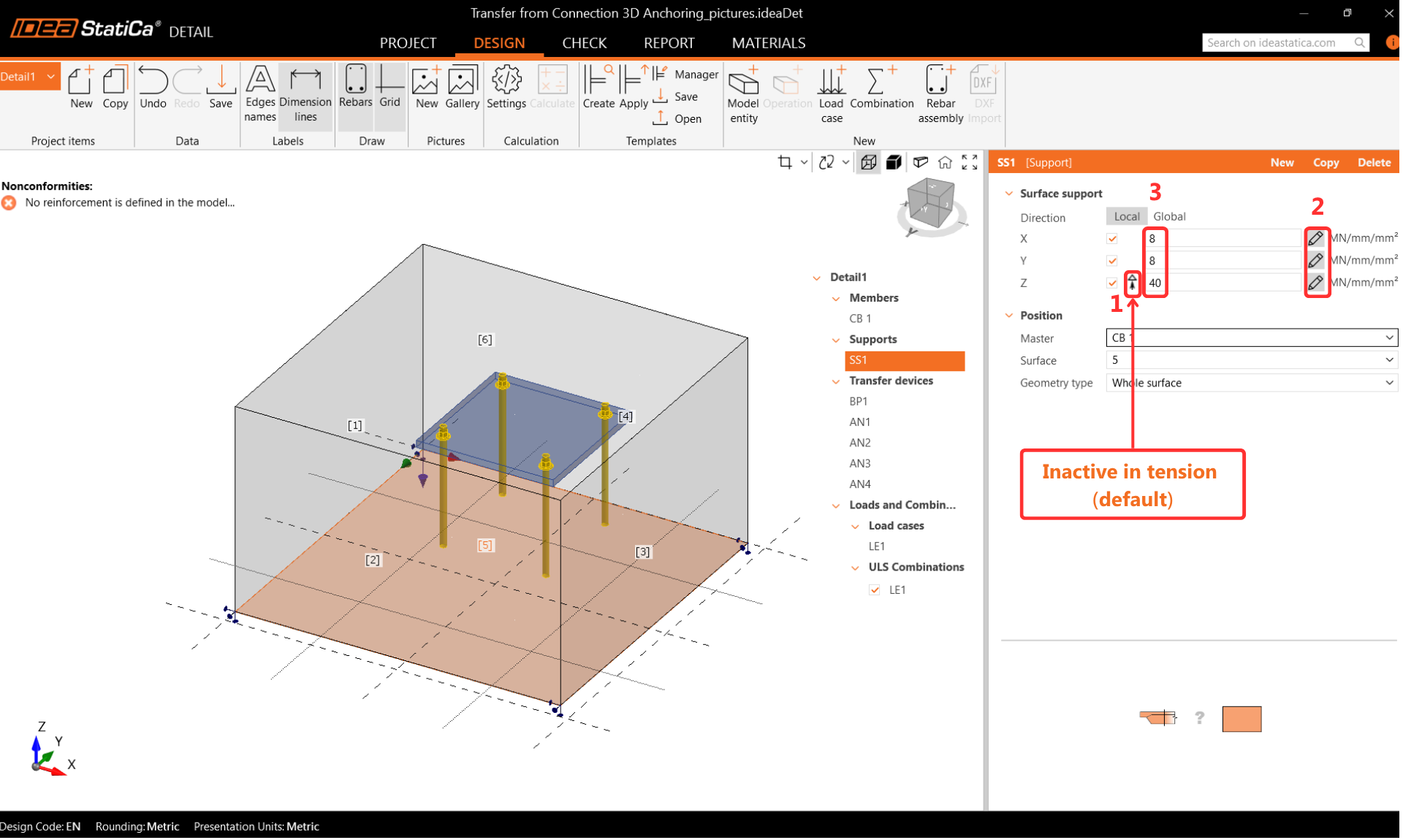
The ground stiffness should be included for accurate design. The Surface Support provides stiffness in all three directions and is set by default to be inactive in tension. Where moments are high, the tension support may disengage during analysis and cause large rotations that lead to model divergence. Caution is needed when setting boundary conditions.
Transfer Devices
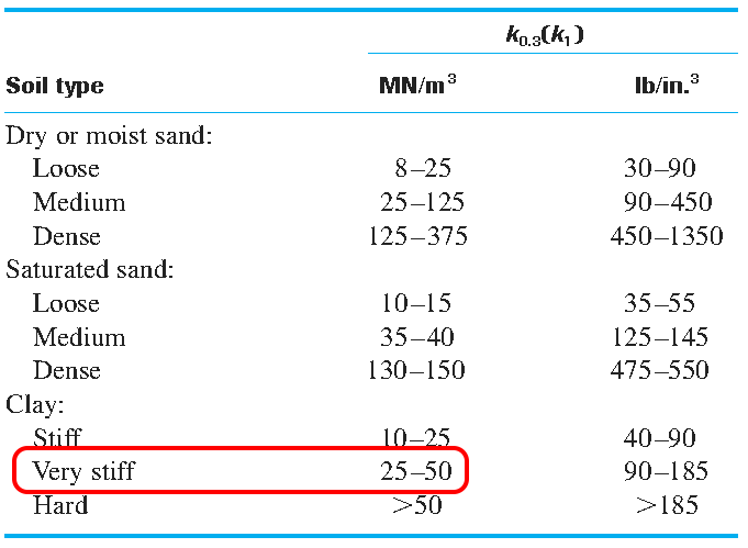
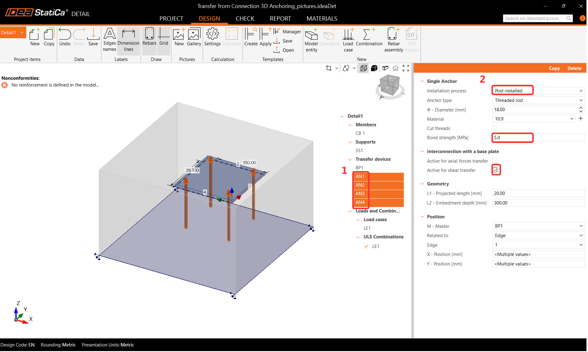
The anchors are carried over from Connection. Cast-in-place anchors are treated with the same bond properties as reinforcement bars. Post-installed adhesive anchors allow customization of bond strength based on the manufacturer's data. Pay close attention to the Interconnection with a base plate settings. When importing from Connection, axial force transfer should be off and shear transfer should be on, because the anchors are loaded directly by forces. When designing from scratch in Detail, both settings should be on. Where shear is transferred through anchors, the user must specify which anchors carry the shear force, in line with EN requirements.
Reinforcement
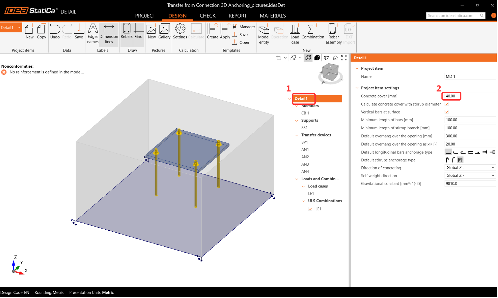
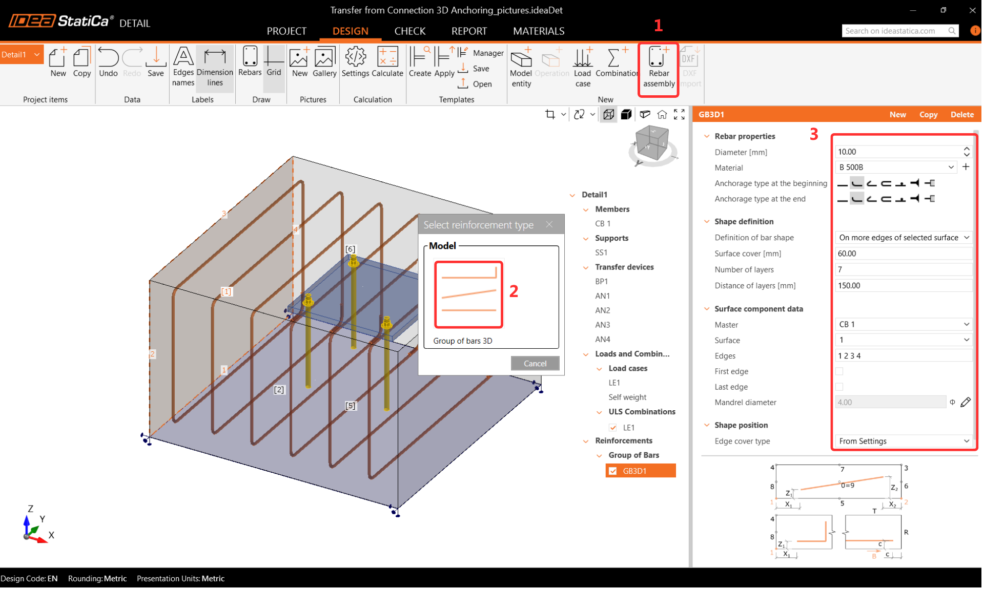
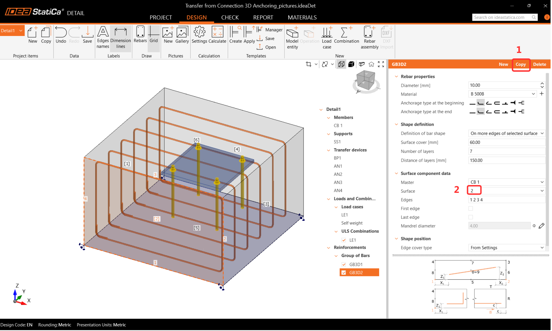
Set the concrete cover to 40 mm as the default for reinforcement. Use the Rebar Assembly operation with Group of bars 3D to define the reinforcement diameter, properties, and geometry. Copy the operation for each reinforcement direction, adjusting the surface and parameters as required. Define shear reinforcement as vertical bars with a perfect bond at both ends.
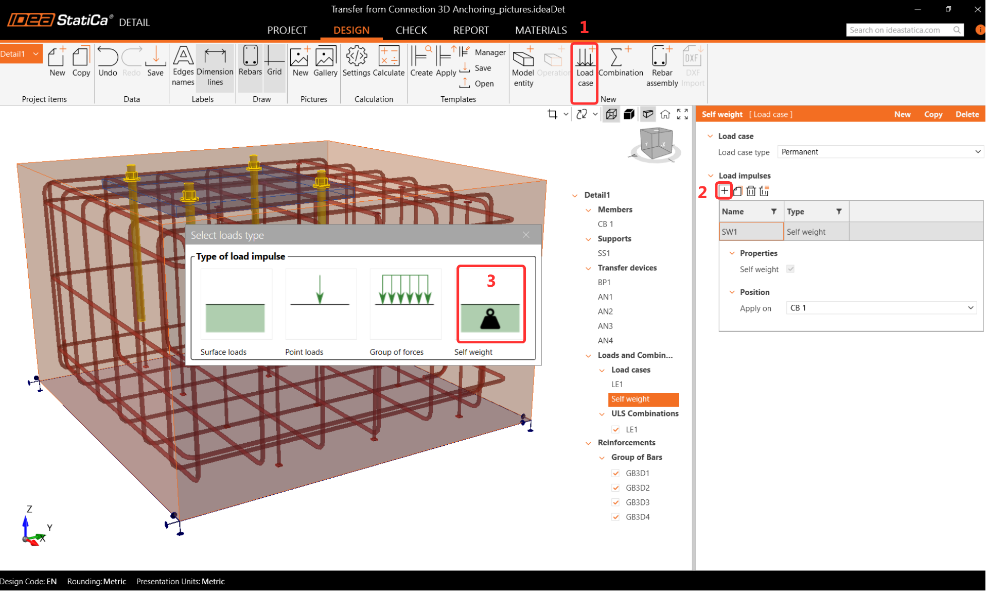
Loads and Combinations
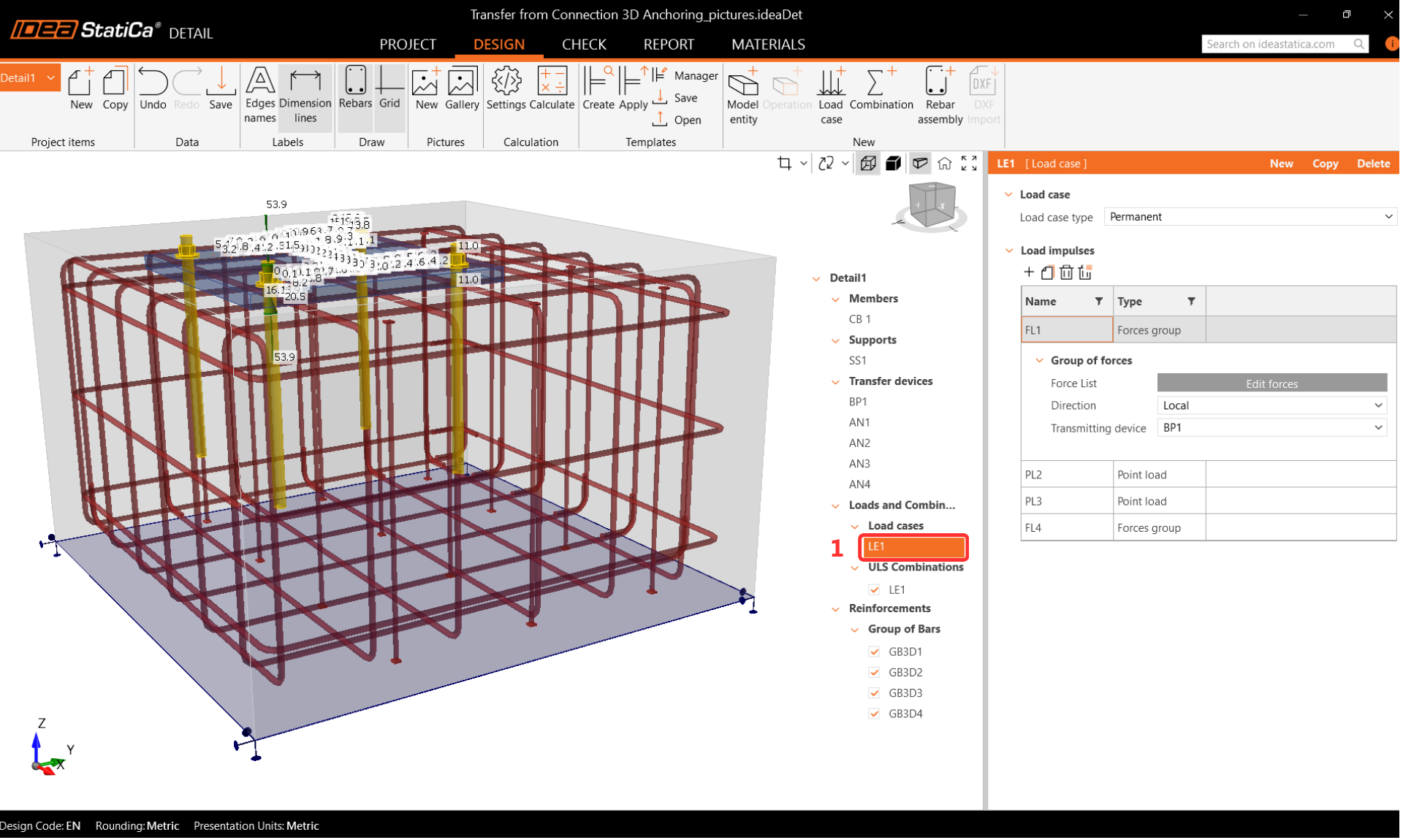
Load combinations are transferred from IDEA StatiCa Connection. Self-weight is defined separately. A combination including self-weight with a factor of 1.35, following EN 1991-1-1, should be created.
Step 6: Calculate in Detail
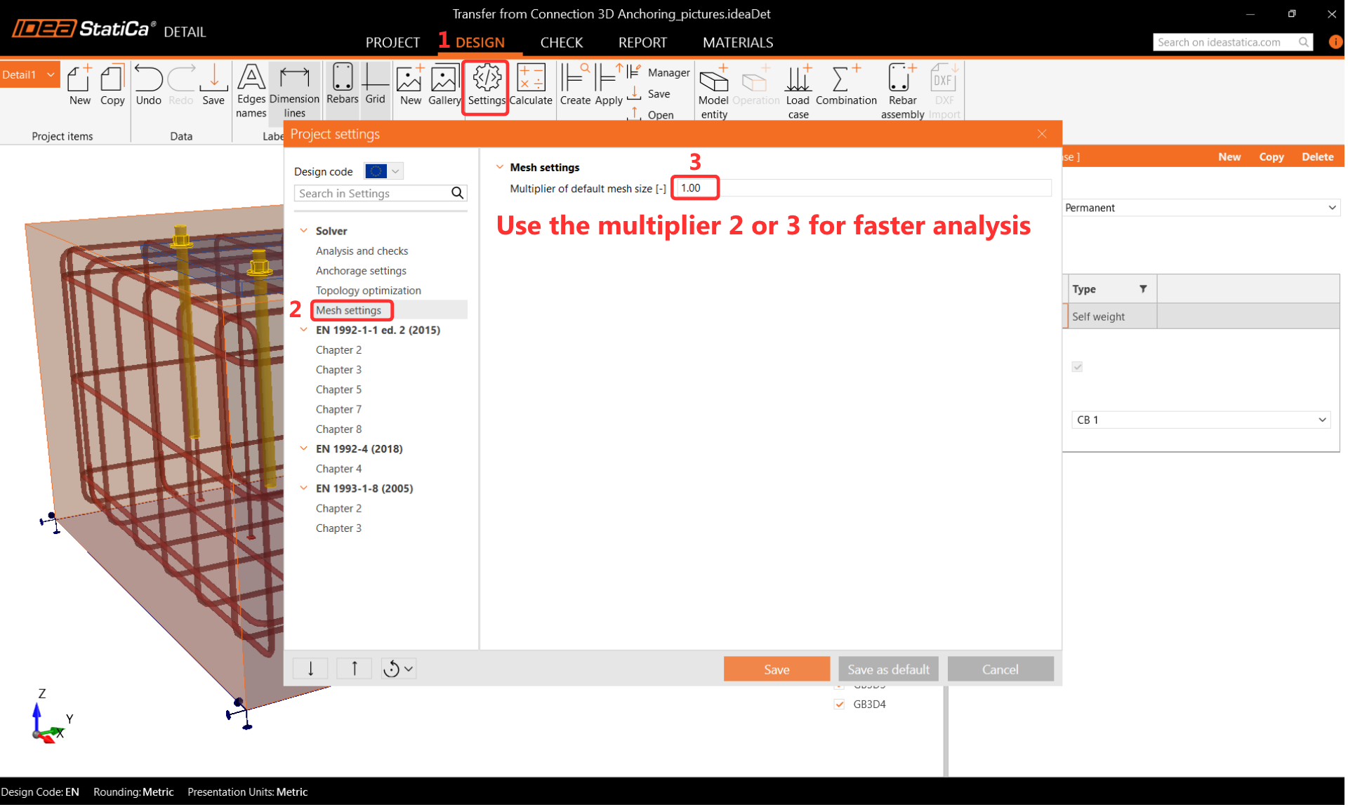
Before running the analysis, set the mesh multiplier to two or three to reduce computation time and identify potential divergence issues. Once the model is confirmed stable, the multiplier can be returned to one for a full-resolution analysis.
Results
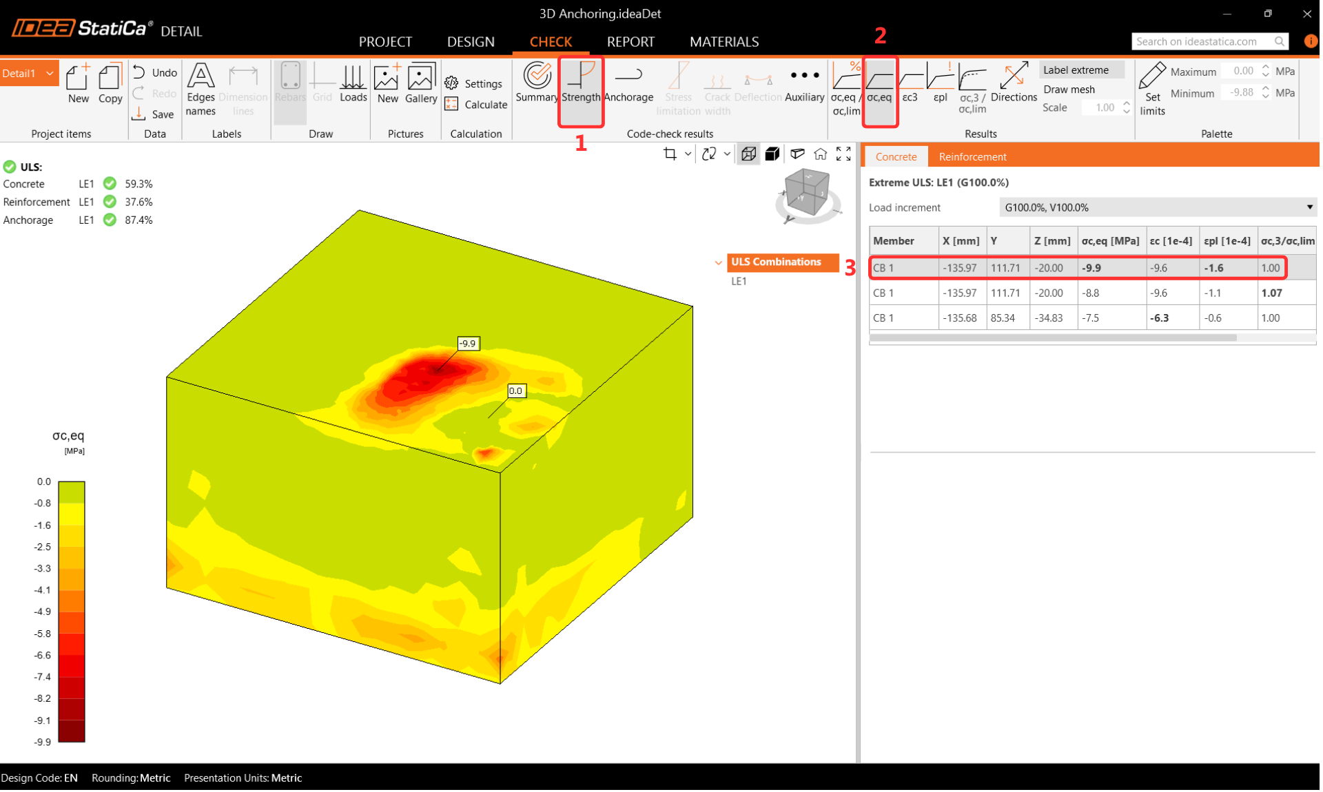
Equivalent Principal Stress
The equivalent principal stress in concrete is determined from the volume behavior of the concrete block. Areas with the highest load are highlighted. The kappa factor is used to account for confinement effects compared to uniaxial compression.
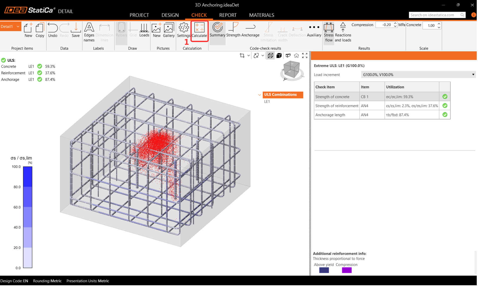
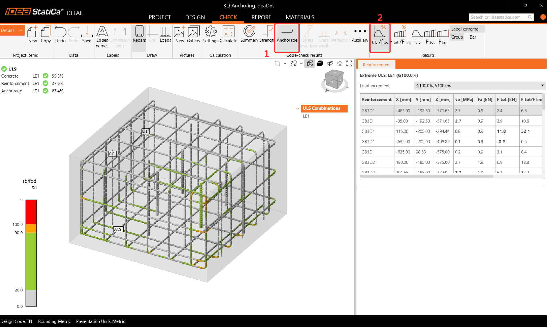
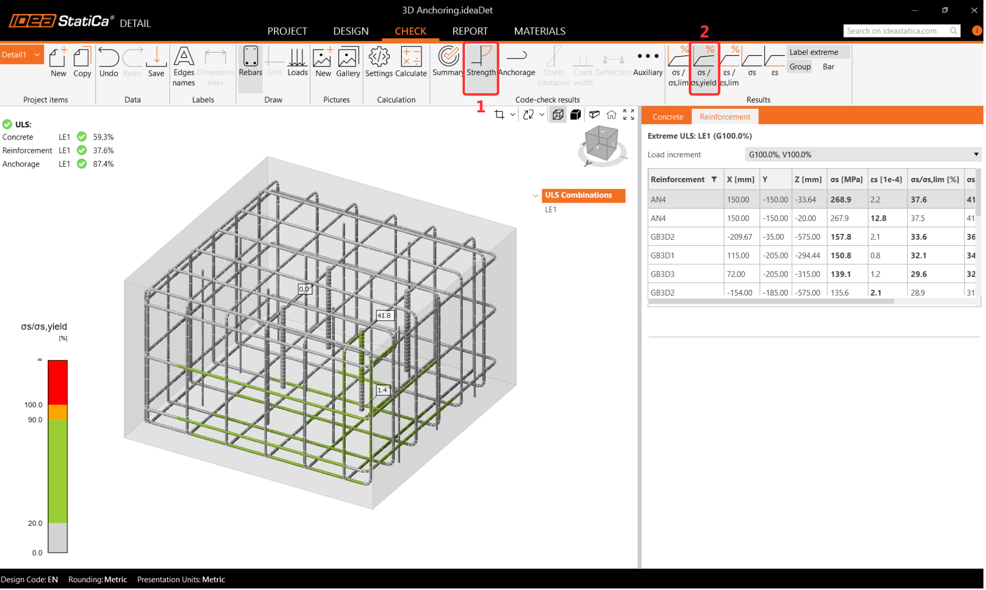
Reinforcement Stress
During the reinforcement check, the anchor closest to the corner is found to be maximally utilized. The reinforcement utilization display clearly shows which bars contribute to load transfer and which prevent concrete cone failure.
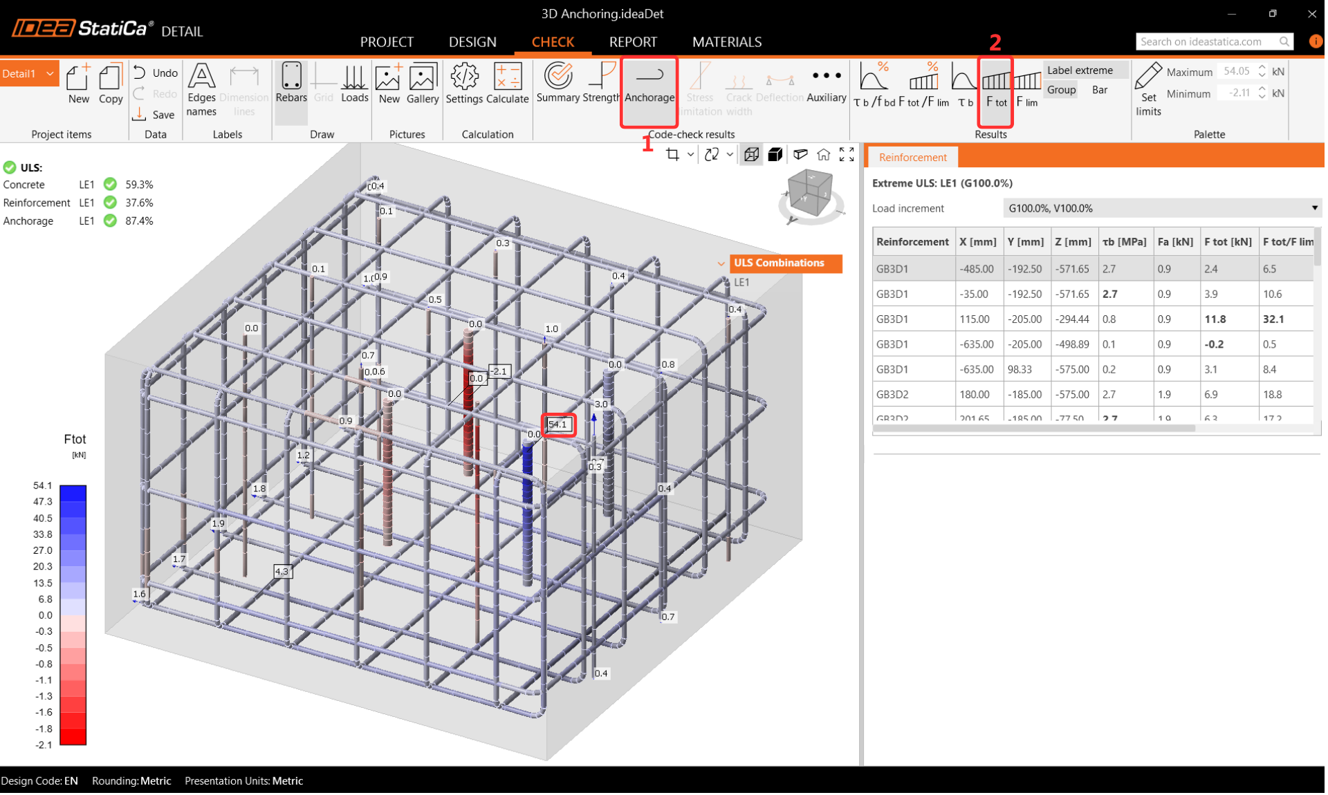
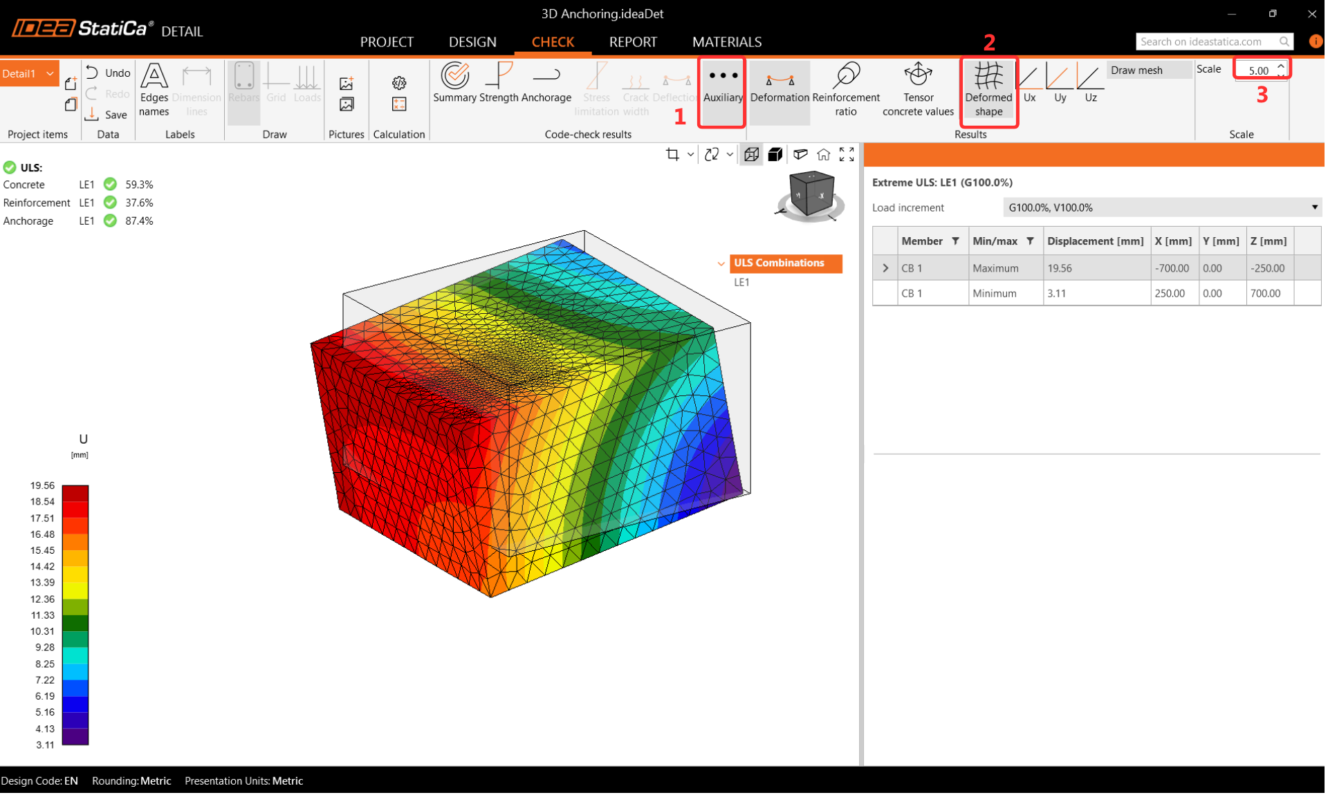
Anchorage and Deformations
Double-check the anchorage settings and enable Total Force in Anchors to review the force distribution. Small differences between Connection and Detail results are expected due to the different calculation approaches for the concrete block. Deformation should be reviewed after analysis to confirm there are no large displacements, rotations, or distorted finite elements.
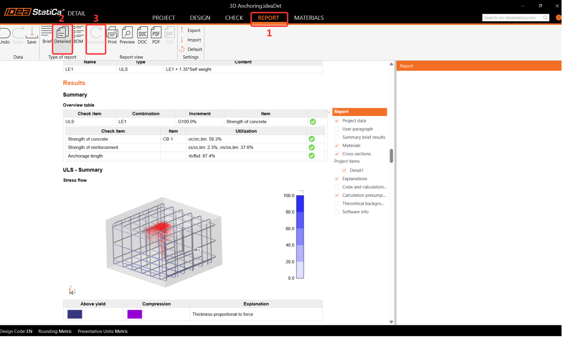
Step 7: Report
IDEA StatiCa Detail provides a fully customizable report that can be printed or saved in an editable format. The report covers the complete connection design verification according to EN 1993-1-8 for the steel part in Connection and EN 1992-4 for the concrete block in Detail.