Overview
The forces in anchors, including prying forces, are determined by finite element analysis. The resistances are then verified against the code provisions of CSA A23.3, Annex D.
Anchor Resistances Evaluated
Anchor rods are assessed according to CSA A23.3-14, Annex D. The following resistances are calculated for each anchor bolt:
- Steel strength in tension (Nsar)
- Concrete breakout strength in tension (Ncbr)
- Concrete pullout strength (Npr)
- Concrete side-face blowout strength (Nsbr)
- Steel strength in shear (Vsar)
- Concrete breakout strength in shear (Vcbr)
- Concrete pryout strength in shear (Vcpr)
The user selects the concrete condition as cracked or non-cracked. The anchor type (cast-in headed with circular or rectangular washers, or straight anchors) is also selected by the user. Pullout strength and side-face blowout strength are evaluated in the software for headed anchors only.
Checks Not Included
The following checks for anchors loaded in tension are not carried out by the software and must be verified separately using the relevant Technical Product Specification:
- Pull-out failure of post-installed mechanical anchors (CSA A23.3-14: D.6.3)
- Bond strength of post-installed bonded anchors (CSA A23.3-14: D.6.5)
Anchors must also satisfy the required edge distances, spacings, and thicknesses to avoid splitting failure, as required by CSA A23.3-14: D.9.
Steel Resistance in Tension
The steel strength of an anchor in tension is determined according to CSA A23.3-14, Clause D.6.1. The calculation uses the effective cross-sectional area of the anchor, the steel resistance factor, the specified tensile strength, and a resistance modification factor.
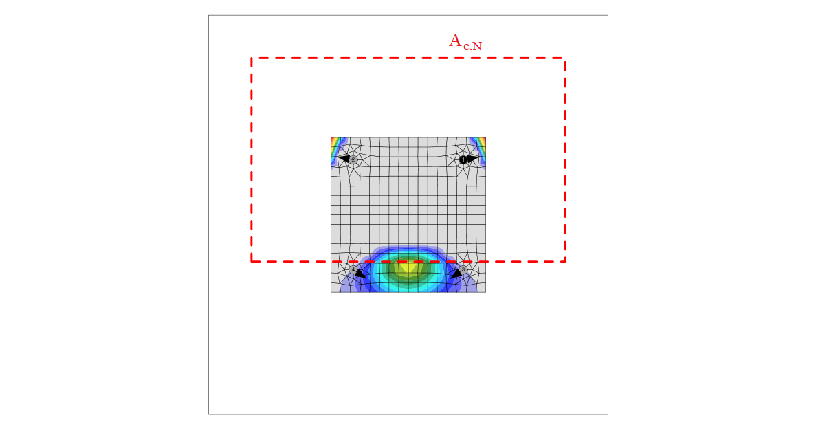
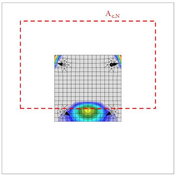
Concrete Breakout Resistance in Tension
Concrete breakout strength is assessed using the Concrete Capacity Design method in CSA A23.3-14, Clause D.6.2. The concrete cone is assumed to form at approximately 34 degrees and is treated as square in plan. Breakout stress decreases as the size of the breakout surface increases. Modification factors account for edge distance, eccentric loading of anchor groups, and concrete condition.
Where anchor reinforcement is developed on both sides of the breakout surface in accordance with CSA A23.3-14, Clause 12, the reinforcement is assumed to transfer the tension forces and concrete breakout strength is not assessed (this can be set in Code setup).
Concrete Pullout Resistance
Concrete pullout strength for headed anchors is defined in CSA A23.3-14, Clause D.6.3. A modification factor is applied based on concrete condition. For anchor types other than headed, pullout strength is not assessed by the software and must be specified by the manufacturer.
Concrete Side-Face Blowout Resistance
Side-face blowout strength of headed anchors in tension is defined in CSA A23.3-14, Clause D.6.4. Reduction factors apply when edge distances are small relative to the embedment depth. IDEA StatiCa checks each anchor independently for side-face blowout strength, using a combined reduction factor that accounts for both edge distance and anchor spacing.
Steel Resistance in Shear
Steel shear strength is determined according to CSA A23.3, Clause D.7.1. Where a mortar joint is present, the steel strength in shear is reduced. Shear on a lever arm, arising from oversized holes or washers added on top of the base plate, is not assessed.
Concrete Breakout Resistance in Shear
Concrete breakout strength in shear is assessed according to CSA A23.3, Clause D.7.2. The shear force is assumed to be carried by the anchors closest to the edge in the direction of the shear. The direction of the shear force relative to the concrete edge influences the breakout strength. Modification factors address eccentricity, edge effects, concrete condition, member thickness, and shear angle.
Concrete Pryout Resistance in Shear
Pryout strength is assessed according to CSA A23.3, Clause D.7.3. The pryout coefficient depends on the effective embedment depth: a value of 1.0 applies for embedment depths below 65 mm, and 2.0 for depths of 65 mm or greater.
Interaction of Tension and Shear
The combined effect of tensile and shear forces on each anchor is assessed according to the interaction equation in CSA A23.3, Figure D.18. The interaction uses the ratio of design forces to resistances raised to the power of 5/3.
Detailing Requirements
Anchor spacing must exceed four times the anchor diameter according to CSA A23.3-14, Clause D.9.2. Edge distances to the steel plate follow the bolt edge distance rules in CSA S16-14, Clause 22.3, with a minimum edge distance of 1.25 times the anchor diameter.